|
a drawing is generated from a design file . the design file must
be open . open the 2x4 lego block design
open the A4 layout drawing and use save copy as to save
it as lego block . open the lego block drawing . select
sheet setup from the drawing menu . and set the
scale to 25:10 (paper 25 . model 10) note: this is the
same as 2.5:1 but prodesktop does not allow decimal points in
the scale setting
select modify and select the text tab and check
the text height is set to 2 . select the terminators tab
and check the length is set to 3 and the width to 1.5 . select
the placement tab and check the above level and along line
orientation are checked . and select OK
select the select annotations tool  and double click on the scale . edit the scale to 2.5:1 and change
the EXAM BOARD text to read LEGO PARTS . edit the name, title
and date text
and double click on the scale . edit the scale to 2.5:1 and change
the EXAM BOARD text to read LEGO PARTS . edit the name, title
and date text
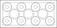
select add modelling view from the drawing menu
. using the from workplane option select the lego block
. check the workplane option is set to base and select
OK . move the plan view into position by dragging on the broken
line surrounding the view
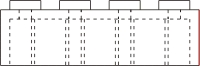
use the select features tool  to select the bottom line of the plan view . select add projected
view from the drawing menu . move the front elevation
into position . the front elevation must be lined up with the
plan view
to select the bottom line of the plan view . select add projected
view from the drawing menu . move the front elevation
into position . the front elevation must be lined up with the
plan view
|
|
|
|
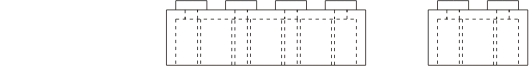
select the plan view with the select views tool  and right click and select align other views . use select
features to select the end line of the front view
and right click and select align other views . use select
features to select the end line of the front view
|
|
|
|
and use add projected view to add the end elevation
|
|
|
|
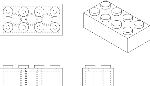
check in the design window that the lego block is in isometric
view and in the drawing window select add modelling view
from the drawing menu . select the from window tab and
select the 2x4block and select OK
use the select views tool to select the isometric view
. and right click and deselect the show hidden lines option
|
|
|
|
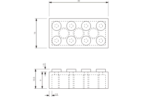
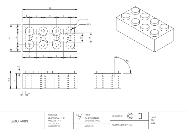
select the linear dimension tool  dimensions are set by clicking (selecting) the line to be dimensioned
from and then clicking and dragging on the line to be dimensioned
to . for example: click on the bottom line of the front view and
click and drag from the top line of the prong to set the overall
height
dimensions are set by clicking (selecting) the line to be dimensioned
from and then clicking and dragging on the line to be dimensioned
to . for example: click on the bottom line of the front view and
click and drag from the top line of the prong to set the overall
height
|
|

|
|
complete the linear dimensions . dimensions need to be lined up
where ever possible . smaller dimensions should be inside bigger
dimensions (projection lines should not cross each other) . very
small dimension numbers (eg the height of the prong and the width
of the shell) can be re-positioned to the right of the projection
line . select the select annotations tool and click and
drag to re-position a number
|
|
|
|
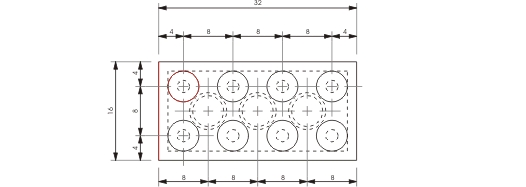
the prodesktop default for dimensioning from a line to a circle
or from a circle to a circle is to dimension to the centre point
of the circle . the centre lines are added automatically
|
|
|
|
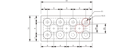
select the diametric dimension tool  and dimension the inner and outer diameters of the hidden prongs
select the radial dimension tool  and dimension the inner and outer radius of the prongs
|
|
|
|
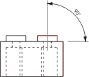
select the angular dimension tool  and dimension from the prong on the side view to the edge of the
block
and dimension from the prong on the side view to the edge of the
block
|
|
|
|
|
| |
|
|